Column heads
A column or point support acting on a slab over its real footprint, elastic, rigid or stiff, so the moment at the column face converges.
Modeling 4 min read
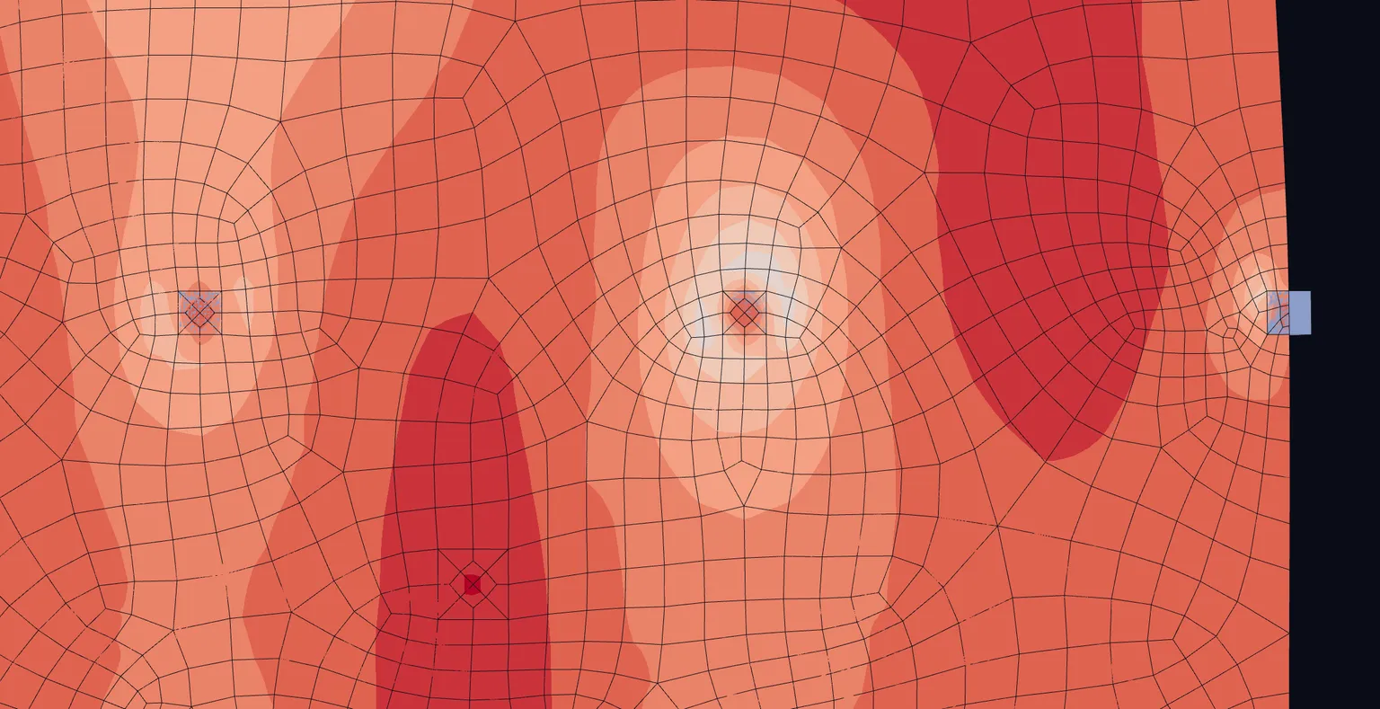
A column modelled as a line meets the slab at one node. That node is a point support in a plate, and the moment over it grows every time the mesh is refined: it is a singular point. A column head makes the column act over its cross-section instead. That removes the singularity at its source. The moment at the column face converges, and the column's own end moment stops depending on the mesh.
The four modes
| Mode | What it does |
|---|---|
| Point | The column acts at one node. The slab peak over it depends on the mesh. |
| Elastic footprint | The slab bears on the column's section on a bed of springs, 4 E / t, as a real joint does. Checked against a 3D continuum model of slab and concrete column, the moment at the column face reads within −3 to +9 %, the column's end moment within −4 %, and no peaks form at the footprint's corners. |
| Rigid footprint | The slab is held rigid in bending over the column's section. Its membrane is left free, so the head does not stop the slab stretching in its own plane. It is stiffer than a real joint: against the same 3D model the moment at the column face reads 13–58 % high, with peaks at the footprint's corners that grow as the mesh is refined. |
| Stiff footprint | The slab over the column's section is made stiffer by a factor: its modulus is multiplied by the Stiff footprint factor, 100 by default, as in SAFE's stiff column zone. |
Elastic footprint is the default for columns in new projects. Stiff footprint lets the head bend with the slab by as much as the factor allows.
The footprint
For a column, the footprint comes from its cross-section:
- A circular or pipe section gives a circle of the section's diameter.
- Any other section gives a rectangle b × h from its outer extents, turned with the section.
Edge and corner columns are handled: the head is the part of the footprint the slab actually covers. A footprint wholly off the plate, one that overlaps another head, or one crossed by a member embedded in the plate is refused: that column stays a point, with a warning that says why.
The mesh is refined automatically around each footprint, so the face is resolved without a mesh refinement of your own.
For the whole project
Project settings › Model › Slabs › Column heads sets the mode for every column: Point, Elastic footprint, Rigid footprint or Stiff footprint. With Stiff footprint selected, the Stiff footprint factor appears below it.
On one column
In the column's properties, under Analysis mesh, Column head offers Project (…), which follows the project setting and is the default, or Point, Elastic footprint, Rigid footprint or Stiff footprint for this column alone. A stiff head on one column can take its own Stiffness factor. Leave the factor empty and the project's factor applies.
On a point support
A point support on a plate can have a head too. Select the node and open the Supports section of its properties. Column head appears when one node is selected and the support holds at least one direction. A point support has no section to take a footprint from, so you give it one:
- Footprint: Rectangle with Width b and Depth h, or Circle with Diameter d. The default is 0.4 × 0.4 m.
- Stiffness factor, when the head is stiff.
A point support's head does not follow the project setting. It stays a point until you set it.
Defaults
| New projects | Projects made before column heads existed | |
|---|---|---|
| Columns | Elastic footprint | Point, set when the project is first opened, so its results do not change |
| Point supports | Point | Point |
| Stiff footprint factor | 100 | 100 |
Turning it off
Set Column heads to Point in the project settings, or set Column head to Point on a single column or support. The column then acts at one node again, and its singular marker returns.
Reading the result
Under an elastic head the slab bends over the column as it would on the real joint, so the plate result there is the design field: read the moment at the column face off the contour, or with a section cut. A rigid head holds the slab flat over the footprint, so read its moment at the face, not over the head. A smoothing region with the Face value method reports it directly, and the project's peak smoothing rule, when you turn it on, takes the face value at every rigid head. An elastic head needs no smoothing.
Something wrong or unclear on this page? Tell us, and it gets corrected.