Reading singular points
Why the peak at a column, a point load or a re-entrant corner grows with the mesh, how plate results mark those points, and what to do at each.
Results & reports 3 min read
A plate model has points where a result has no finite value. Refine the mesh at one of them and the peak grows without bound, so the number on screen describes the mesh, not the structure. Plate results mark every such point, so you know which peaks are not design values before you read one.
What counts as a singular point
The hover card names the reason, in the words of the first column:
| Reason shown | Where | Usual way to a design value |
|---|---|---|
| Point load | A nodal load on a plate | Spread it over its contact area |
| Point support | A support at a single plate node | A column head over its bearing area |
| Column | A column meeting the slab at one node, without a head | A column head |
| End of a line support | Where a line support stops inside or along a plate | A smoothing region |
| Re-entrant corner (θ°) | An internal corner of the outline or an opening | A smoothing region |
| End of a member in the plate | Where a wall, rib or beam embedded in the plate ends | A smoothing region |
The first three are a finite force or reaction delivered through zero area. The last three are geometry: an abrupt end or an internal corner with zero radius. In each case the elastic solution itself is infinite at the point. That is a property of the idealisation, not of the mesh, so no mesh fixes it.
How they are marked
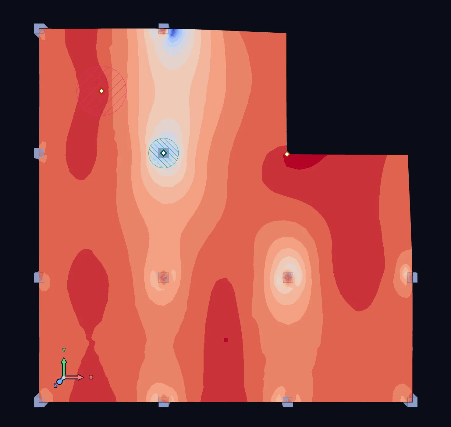
Each singular point carries a hollow diamond on plate results:
- Amber: nothing deals with the peak yet. The value at the point depends on the mesh.
- Teal: a smoothing region covers the point, and the result shown there is the smoothed one.
A column with a head is not marked: the head removes the singularity at its source.
The hover card
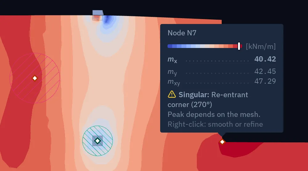
Hovering a singular point keeps the usual value readout and adds a short status line under it:
- Singular: followed by the reasons, then Peak depends on the mesh. The value in the readout is not a design value.
- Smoothed (average): (or whichever method the region uses) when a smoothing region covers the point. The readout then gives the smoothed value with the unsmoothed peak beside it, so the raw number is never hidden.
- Right-click: smooth or refine is a reminder of the shortcut below.
Right-click: smooth or refine
Right-click a singular point and the top of the node menu reads Singular point · followed by the reasons, with two actions:
- Smooth the peak here adds a smoothing region on the node, with the project's method and components. Select it to change its size or method.
- Refine the mesh here adds a mesh refinement on the node.
Both create ordinary model objects. They show in the properties of the node, and you can edit or delete them like anything else.
Which fix to use
- A column or a point support with a real footprint: give it a column head. It removes the singularity rather than treating the result, and the column's own end moment stops depending on the mesh.
- A point load with a real contact area, such as a wheel, a post or a machine foot: spread it. The total force stays exact.
- A point that stays singular, such as a corner, the end of a wall or a support you keep as a point: put a smoothing region on it and read the averaged value or the value at its face.
Refining the mesh on its own is not a fix. At a singular point it only makes the peak larger. Refinement earns its place next to a fix: round a column head, or inside a smoothing region so the average is taken over a real area.
Showing or hiding the markers
The markers are on by default. Switch them off in the viewer's Style menu with Mark singular points. The switch is there in 3D viewers showing plate results. Analysis › Verify › Singularities turns the marks on or off in every 3D viewer, on the model and over results. Hiding the markers changes nothing but the drawing: the results are the same either way.
Something wrong or unclear on this page? Tell us, and it gets corrected.