Smoothing regions
Average, ring fit or face value over a region at a column, point load or corner, applied per load case, for plate design values that converge.
Results & reports 4 min read
A smoothing region replaces the plate result inside an area with a value that does not depend on the mesh. Put one on a singular point and the peak there becomes a number you can design with. It is the standard treatment: the mean over a small area, or the value at the column face, rather than the value at the node.
Smoothing works on results only. It never changes the solve, and with no region set, every result is bit-for-bit what it was.
Measured
- raw, at the support node
- mean over a 0.4 m circle
| mₓ at the support, kNm/m | h = 0.2 m | h = 0.1 m | h = 0.05 m | last halving |
|---|---|---|---|---|
| raw, at the support node | 24.7 | 33.1 | 41.3 | +24.8 % |
| mean over a 0.4 m circle | 14.83 | 14.81 | 14.91 | +0.7 % |
The raw value at the support grew by a quarter on the last halving of the element size. The mean over a 0.4 m circle stayed within 0.7 % across all three meshes.
Where a region sits
A region is an object in the model, tied to something in it, so it moves when the model moves:
| Tied to | Shape | Size |
|---|---|---|
| A node | Circle (default) or Rectangle, which can be turned | Radius 2 × t; sides 4 × t |
| A column standing on a slab | Circle where the column meets the slab | Radius 2 × t |
| A member or wall lying in a plate | A strip along it | Strip width 4 × t |
| A plate edge | A strip along the edge | Strip width 4 × t |
| Three or more nodes | A polygon through them, the Corner nodes | The polygon |
Here t is the plate thickness. The sizes are defaults: type a value into Radius, Side a, Side b or Strip width to override one.
Methods
| Method | What it does |
|---|---|
| Average | The area mean of the element results over the region. A strip averages across its width only, so a support moment along a wall keeps its variation along the wall. |
| Ring fit | Fits a linear field in a ring just outside the region and carries it inside, keeping the slope. |
| Face value | The value at the region's boundary. At a column, that is the moment at its face, in the spirit of EN 1992-1-1 §5.3.2.2(4). |
| Zero | Clears the inside of a column. Offered on a region, not in the project rule. |
Average suits a point support or a point load you keep as a point. Face value suits a column, where the design moment is taken at the face. Ring fit keeps a gradient across the region that an average would flatten.
Components
Components decides what a region smooths: Moments (the default), Moments and shears, which adds the transverse shears, or All. Anything not selected is shown raw inside the region.
How it is applied
Smoothing is applied to each load case before combination. Combinations are then exact, because a combination of smoothed cases is the same as smoothing the combination, and envelopes are taken from the smoothed combinations afterwards.
Refine the mesh inside is checked on every new region. The mesh inside the region is then refined, so the average is taken over a real area rather than over whatever few elements happen to touch it. Uncheck it to leave the mesh alone.
Adding one
- Right-click a singular point and choose Smooth the peak here.
- Right-click a node or a member and choose Add smoothing region.
- Right-click a plate edge and choose Add smoothing region on this edge.
- Select three or more nodes, right-click and choose Smoothing region through … selected nodes.
- In the properties of a node, member or plate, the Smoothing regions section lists the regions on it, with an Add button.
Select a region to edit its size, Method and Components. Method and components default to Project (…), which follows the project rule below. To delete a region, right-click it and choose Delete smoothing region, or select it and delete it.
The project rule
Instead of placing regions one by one, you can have the project smooth every singular peak. Project settings › Results › Plate results › Peak smoothing at singular points:
| Setting | Options | Default |
|---|---|---|
| Peak smoothing at singular points | Off, Points, corners and column heads | Off |
| Smoothing method | Average, Ring fit, Face value | Average |
| Smoothed components | Moments, Moments and shears, All | Moments |
| Radius × thickness | Radius of each automatic region, as a multiple of the plate thickness | 2 |
With the rule on, every point load, point support, column and re-entrant corner is smoothed, and the face value is taken at every rigid column head. A column without a head is smoothed over the circle round its cross-section: half its diagonal plus half the slab thickness. An elastic head needs nothing: the slab bends over the column, and its field is the design field.
In the viewer
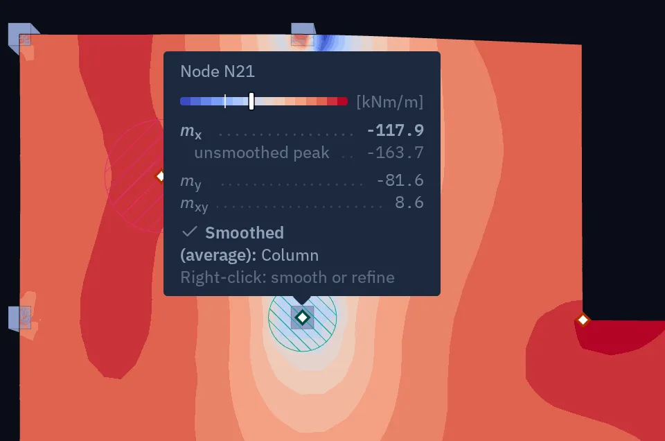
Smoothed areas are hatched in teal on the plate as drawn, on the top face of a 3D slab or the mid-plane of a flat one, and they follow the deformed shape. Pins and the value readout give the unsmoothed peak beside the smoothed value.
Two switches in each viewer's Display sheet:
- Smoothed peaks shows smoothed results when on, the default, and raw results when off.
- Smoothing areas shows or hides the hatching. It is on in model views and off in result views.
Defaults
| Default | |
|---|---|
| Project rule | Off |
| Method, components | Average, moments |
| Radius of a circle | 2 × plate thickness |
| Refine the mesh inside | On |
| Smoothed peaks in a viewer | On |
| Smoothing areas drawn | In model views; hidden in result views |
Turning it off
- For one viewer: switch Smoothed peaks off in its Display sheet. The regions stay; the viewer shows raw results.
- For one region: delete it.
- For the automatic regions: set Peak smoothing at singular points to Off.
What it does not do
- It does not correct a wrong model. If the peak is wrong because a support or a load is wrong, a smoothed value is the same mistake averaged.
- Smoothing regions are not carried by IFC export.
Something wrong or unclear on this page? Tell us, and it gets corrected.