Ribbed slabs
Ribs that work with their slab as T-beams — the eccentric web, T-section forces, effective widths to EN 1992, EN 1994, ACI 318 and AISC 360.
Modeling 20 min read
A rib is a member that works with the slab it hangs under. Together they form a T-beam: the rib is the web and a strip of the slab is the flange. Elementarium analyses the slab as a plate and the rib as an eccentric member. It then reports the rib's forces as those of the whole T-section, because that is the section you design. This page covers how a rib is modelled, how the T-section forces are obtained, the effective width rules, and the three ways to create ribs.
What a rib is in the model
A rib is an ordinary 3D beam with two additions:
- It is connected to a plate. The plate lists it among its connected members, so the mesher embeds it in the slab. The rib and the slab share one chain of nodes along the rib (see How other things attach).
- It is marked as a rib. The mark records where the web sits and how wide a strip of slab its results take in. Everything else a member has still works: section, material, loads, releases, groups, tables and steel design checks.
The rib's section is the web only: the part below the slab, for example a 150 × 300 mm rectangle. The slab is already the flange. If the rib's section is a T or an L whose flange is about as thick as the slab, the rib's properties warn that the flange is counted twice and ask you to use the web only.
Where the web sits
Web in the rib's properties sets the position, and the member's eccentricity follows from it:
| Web | Eccentricity |
|---|---|
| Below the slab (default) | : the top of the web flush with the soffit |
| Above the slab | : an upstand, its bottom flush with the slab top |
| In the slab's mid-plane | 0 |
| Custom offset | Whatever you type |
Here is the slab thickness and , are the distances from the web's centroid to its top and bottom fibres. For a symmetric web of depth hanging below, : a 300 mm web under an 80 mm slab sits 190 mm below the slab's mid-plane. The extents come from the section's outline, so a steel I with unequal flanges also sits flush.
The rib's local axes follow the slab: local is the slab normal, pointing up on a floor. The app writes the eccentricity and the axes again whenever the slab thickness, the section or the web position changes. Typing your own value into the eccentricity switches the rib to Custom offset. A rib under two slabs of different thickness hangs from the thicker one.
The offset is a member eccentricity, not a rigid arm. That matters for the forces below: a rigid link crossing a cut carries a force that the T-section forces cannot see.
How a rib works as a T-beam
The analysis needs no effective width. The slab is meshed whole and the rib hangs off it at its offset. The composite action comes from that offset, and the shell elements carry shear lag across the slab by themselves. The effective width is a design matter: it says how much of the slab to count with the rib when its forces are read.
The consequence is that the bare member's forces are not design values. When the T-beam sags, the slab above is compressed and the web below is pulled. The member therefore carries a large tension, and only a part of the T-section's moment. Most of the moment is the member's tension times its lever arm to the slab.
Rib forces
A rib's T-section forces are what the member and the strip of slab beside it carry together across a cut. The solver works them out as a free body at every node of the rib's analysis chain:
- Cut through the node, across the rib and the strip of slab of the integration width.
- Sum the nodal forces of the elements on one side of the cut, , at the nodes the two sides share. That is exactly the force the other side transmits.
- A shell element counts by the share of its area inside the strip. This is exact where the strip's edges lie on element edges.
- Take the moments about the T-section's elastic centroid, with the member's area and axis weighted by its modulus against the slab's.
The result is , , , , and in the member's own local axes and sign convention, so the rib's diagram is drawn exactly as a member's would be. Because the cut is a free body, the forces are in equilibrium with every load and reaction on any mesh. Integrating the slab's stress field across the cut would understate the moment next to a support. In our test suite, a simply supported rib that takes in the full width of slab between its neighbours gives and .
Each node has a value just before it and one just after it. The step between them is whatever acts at the node: a support, a column, a crossing rib. The diagrams draw it as a step. T-section forces combine and envelope like every other result.
Reading them
- Diagrams. A rib's force diagrams show the T-section by default. Ribs in a viewer's Style menu switches between T-section and Member, for that viewer only. Two viewers side by side, one of each, show why a rib carries tension.
- Hovering a rib adds two rows to the readout, member alone and slab strip, which together make the T-section value. The caption gives the width integrated there, T-section, b = …, and the flange: flange F = …, shear flow v = …. The flange force is , and the shear flow is the longitudinal shear the web passes into the flange, the of EN 1992-1-1 §6.2.4. The breakdown is not shown on an envelope.
- Result tables of element forces have the same T-section / Member switch.
- Rib widths in a 3D viewer's Display sheet draws every rib's strip on its slab. A selected rib always shows its own.
The width is read off a solved model, so changing a width or a width rule re-reads the forces from the same solution. It never solves again.
A member's own forces on a slab
A member tied to a slab along its length, a rib or an edge or downstand beam, takes the slab's shear only at the nodes they share. As the solver gives them, its own forces therefore step at every node and swing inside every element, however fine the mesh. They are right at each element's middle. So Elementarium draws such a member through its elements' midpoint values, straight between them. The steps that are artefacts go, and the real ones stay, because the line breaks at every node where something acts: a support, a load, another member, a hinge line, or the slab ending or changing under it. Where the member hangs below the slab, its vertical shear is read from the slope of its moment about the slab's face, since the slab's shear flow enters it along that face.
Smooth members on slabs, in a viewer's Style menu, is on by default and applies to every view, table, check and report. Switch it off to see every member as the solver gave it. It is a project setting, Project settings › Results › Ribs › Members on slabs, so it is saved with the model and everyone working on it reads the same forces. In an example, or a project you can only view, the switch changes your own view alone.
The effective width
Width in a rib's properties chooses how wide a strip the T-section takes in:
| Width | Strip on each side |
|---|---|
| Effective width (default) | The code's effective flange width, per node along the rib, from the spans found on it. Shown with the rule, for example Effective width (EN 1992). |
| All available slab | Half-way to the next parallel rib, or all the way to the slab edge. The statics check: the T-section then accounts for the whole slab. |
| None — member only | No strip: the bare member. |
| Typed | Flange −y and Flange +y, constant along the rib, measured from the member axis. |
Below the width, the properties draw the Integration width along the rib with the derivation for one side, and state: Affects the T-section results only — the slab is analysed as a plate.
The slab available on each side
Every rule is capped by the slab there is. At each point along the rib, the app looks square to the rib, in the slab's plane, on each side, and stops at the first of:
- the slab's outline or the rim of an opening: the full distance counts;
- another member in the slab running within 10° of parallel: half the distance counts, and the other half belongs to that member.
Ribs that cross, as in a waffle, do not limit each other. A rib along a slab edge finds no slab on its outer side and becomes an L-beam without any input. With Effective width or All available slab, two neighbours' strips cannot overlap. Typed widths are taken as typed: a width past half-way to the neighbour counts that slab twice.
EN 1992 and ACI 318 measure the available width from the face of the web. The app measures from the member axis and takes off half the web width : the contact width at the top of the web, which for a steel I-beam is its top flange. The strip on each side is then
AISC 360 and EN 1994 measure from the web's centreline, so nothing is taken off or added back: the rule's width is the strip, capped by the slab available.
Spans along the rib
The code rules need spans. The app finds them on the rib itself, at its nodes: its two ends and any node along it. A node holds the rib when it has:
- a support holding the slab's out-of-plane direction,
- a column framing in (a member more than 30° out of the slab's plane),
- a wall, i.e. another plate whose edge passes through the node,
- a line support the node lies on,
- a beam crossing it in the slab, or a crossing rib at least 1.5 times deeper.
Ribs of the same depth crossing each other do not hold each other. In a waffle bearing on its edges, every rib therefore spans edge to edge.
Between two holding points is a span; past the last one is a cantilever. Each point of the rib falls into a zone, with the zones of EN 1992-1-1 Fig. 5.2:
| Zone | Where | to EN 1992 |
|---|---|---|
| Single span | Held at both ends only | |
| End span | One end at a held rib end | |
| Interior span | Between two interior supports | |
| Interior support | Within of it, on each side | |
| Cantilever | The overhang and its support's zone |
So one continuous rib gets a narrower flange over its interior supports, with no need to split it into members. Width changes between zones from one node to the next.
Under the width diagram the properties say how many support points were found. With Effective width, every node of the rib is listed with a check box, Holds the rib: a span ends here, to overrule the detection. A rib with nothing holding it is read as one simply supported span: Nothing found holding the rib — read as one simply supported span. Fig. 5.2 assumes adjacent spans within 2/3 to 3/2 of each other and a cantilever shorter than half its back span. Outside that, the width is still computed and the diagram adds spans outside EN 1992 Fig. 5.2 limits.
l₀ in the properties replaces the reference length for the whole rib. For ACI 318 and AISC 360 it replaces the span.
The four rules
| Rule | Clause the app cites | Width on each side, from the line the code measures from |
|---|---|---|
| EN 1992 | EN 1992-1-1 5.3.2.1 | |
| EN 1994 | EN 1994-1-1 5.4.1.2 | |
| ACI 318 | ACI 318-19 Table 6.3.2.1 | Slab on both sides: . One side: |
| AISC 360 | AISC 360-16 I3.1a |
- EN 1992: by zone from the table above. .
- EN 1994: by zone from Fig. 5.1: in an end span, in an interior span, over an interior support, for a cantilever, and for a single span. The width runs linearly over from each support to the span's value, and at an end support the span's value is multiplied by . Setting l₀ replaces all of this with one length.
- ACI 318: is the slab thickness and the slab available from the web face. is the clear span between the faces of the support points it found, taking half a column's or wall's width off each. Over an interior support it takes the shorter of the two spans, and on a cantilever the overhang.
- AISC 360: is the span between support points, centre to centre. Over an interior support it takes the shorter of the two spans, and on a cantilever the overhang.
Which rule a rib follows
Project settings › Results › Ribs › Effective width sets the rule for every rib:
- By material, the default, picks by the rib's material and the project's design code. A concrete rib gets EN 1992, or ACI 318 on US codes. A rib of any other material, such as a steel beam under the slab, gets EN 1994, or AISC 360 on US codes.
- EN 1992, EN 1994, ACI 318 or AISC 360 applies that rule to every rib.
Rule in a rib's properties overrides it for that rib. Project (…), the default, follows the project setting and names the rule it resolves to. The setting changes results only, so a solved model re-reads its rib forces without solving again.
Worked example
A concrete rib, continuous over two equal spans of m, at m centres, with a web m under a slab m. The slab available on each side, from the web face:
EN 1992, in an end span ( m):
EN 1992, over the interior support ( m), within 1.2 m of it on each side:
ACI 318 on the same rib, with slab on both sides ( m, m):
The ACI value is the same over the support, since both neighbouring spans are 8 m.
At close spacing, the cap decides. The ribs of the generator's default slab are 150 mm wide at 0.75 m centres, so m, and every rule gives the full 0.75 m.
Rib torsion
A downstand web and the slab above it twist together. Project settings › Model › Slabs › Rib torsion sets the torsion constant a rib is solved with:
- Full depth, the default: the web twists over its whole depth , less the
strip of slab directly above it, which the shell already twists:
is the Saint-Venant constant of a solid rectangle , : . Against a 3D solid model, the torque came out within 0.3–7 % with this constant, and 5–12 % off with the web alone. - Section's own: the web below the slab alone, as its section states.
Torsion in a rib's properties overrides the setting for that rib, and shows the section's next to the one used. The full-depth constant applies to rectangular webs only. A rib of any other section keeps its section's . The section itself is not changed.
For a 150 × 300 mm web under an 80 mm slab: m⁴, less m⁴, gives m⁴.
Rib torsion changes stiffness, so changing it means a new solve.
Meshing a rib
A rib's diagram is only as good as its elements per span: the T-moment's error goes with , about 1.6 % at 8 elements per span and 0.4 % at 16. Project settings › Mesh › Members › Rib elements per span, 12 by default, sets the floor.
The rule becomes a maximum element length along the rib: its shortest span divided by the count. A rib over 8 m spans, at 12 per span, gets elements no longer than 0.67 m. Where the slab around it is meshed finer, the rib follows the slab. Where a member or project rule asks a span for more elements, the cap tightens. The rib's nodes are not fixed in advance, so the bays between ribs still mesh into regular grids. See Choosing element size.
The grid holds up to a refinement round a column, too. On a 16 × 12 m slab with ribs every 1.5 m both ways, on two columns with a 0.1 m refinement round each, at 0.7 m elements, 154 of 721 elements are below quality 0.75, against 1073 of 1701 in release 0.7.1. Two-way ribs mesh on a slab on a grid of columns or with a skewed side as well.
Crossing ribs need no node of their own in the model. The mesher joins two ribs where they cross in the slab, and both chains pass through the node it makes there.
Creating ribs
Draw them one by one
Draw rib sits in the Slab split of Home › Geometry and Model › Geometry. Click two nodes that lie on one slab, inside it or along its edge. The rib is created between them, connected to that slab, with the web and settings of the last rib you made (a 150 × 300 mm web for the first one) and the slab's material. If the two nodes do not lie on one slab, a warning says so and nothing is drawn.
A member that already lies on a slab becomes a rib in its own properties. The Rib section has a switch, Works with P1 as a T-beam. If the member is not yet connected, it reads Connect to P1 and work with it as a T-beam, and switching it on also connects the member to the plate. With several members selected, one switch makes them all ribs. Switching it off makes the rib a plain member again; it keeps its offset and axes but no longer follows the slab.
The Ribs in a slab dialog
Ribs, in the same Slab split, or Add ribs… in a plate's properties opens Ribs in a slab. It lays a whole pattern into one slab:
- Slab: pick it from the list, or Pick it in the model. A slab selected before opening the dialog is already chosen.
- Layout: One way (ribs along X or Y), Waffle (both ways, crossing in a grid) or Angled (parallel ribs at an Angle from X).
- Spacing, Ribs (the count) and Edge margin. Spacing and count are one decision: the one you typed last drives. The margin is half a spacing until you set it, and the ribs are centred on the slab. In a waffle each way has its own column, Along X and Along Y, linked by Same both ways. Typing a count unlinks them.
- Ribs along the slab's edges too adds edge ribs, which become L-beams.
- Web: Below, Above or Mid-plane, with its Width and depth, and the Material (the slab's by default).
The dialog draws the slab as the viewport shows it, with its setting-out dimensions, and a dimensioned section across the ribs with the clear distance between webs. The field you are in lights its dimension. Each rib is one member across the whole slab, clipped by the outline and any openings. If the slab already has ribs, Replace the … ribs P1 has now is ticked, and they are deleted first. The footer counts the ribs and their crossings. Everything is added in one step, so one undo removes it.
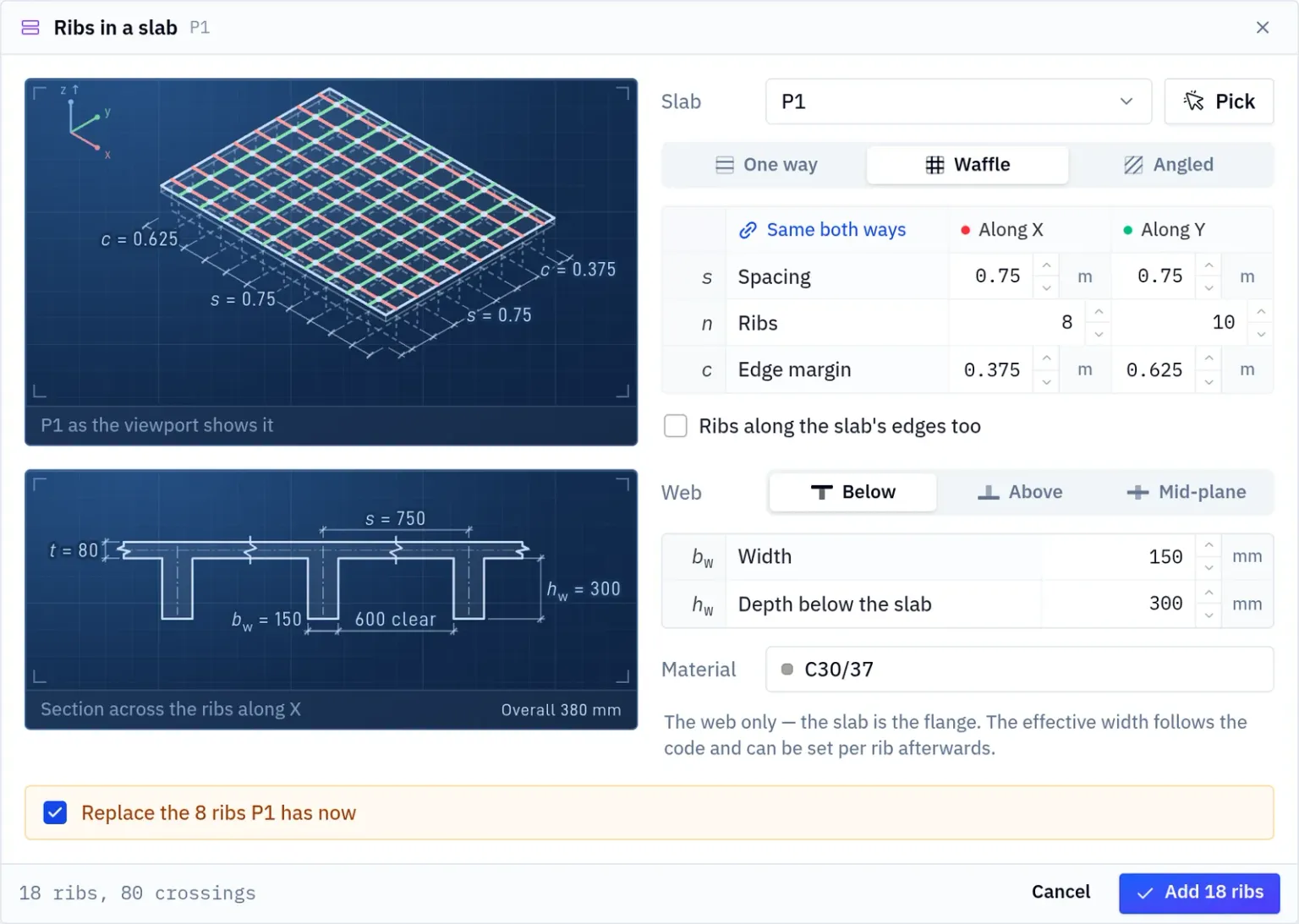
The width of each new rib is Effective width, by the project's rule. Change it per rib afterwards.
The Ribbed slab generator
Generate has a Ribbed slab under Surfaces & shells: one slab, with downstand ribs one way or both ways. Each rib is one member across the slab, working with it as a T-beam with the effective width.
| Field | Default (SI) |
|---|---|
| Ribs | One way or Waffle |
| Slab length × width | 8 × 6 m |
| Rib spacing | 0.75 m, ribs centred on the slab |
| Rib width × Rib depth below slab | 150 × 300 mm |
| Thickness | 80 mm |
| Surface load | 5 kN/m² |
The slab is pinned at its corners and at every rib end on its supported edges: the two ends of a one-way slab, all four edges of a waffle. The ribs are in the slab's material. Like every surface generator, it needs a 3D frame or general 3D model. See Structure generators.
Tables, report and exchange
- The Ribs table lists every rib with its Slab, Web section, Spans and Length.
- The report has a Ribs section: slab, web and effective width per rib, with the width derivation. It is in the Design only and Full calculation presets.
- SAF export writes a rib as a rib of its slab, with the widths resolved to numbers. SAF import reads ribs back.
What ribs do not do
- Design the T-section. Elementarium has no concrete design module. You get the T-section forces and the width; flexure, shear and reinforcement are yours.
- Feed the steel checks. A steel design check on a rib checks the member's own section with the member's own forces, not the T-section's.
- Reduce the slab results. Slab contours are the full field, including the strip a rib takes in. If you design both the slab and the ribs, do not count the strip in both.
- Change stiffness with the width. The width only changes how results are read. The stiffness is the slab and the eccentric web, whatever the width.
- Model partial shear connection. A rib is fully connected to its slab. A slab merely resting on a beam is a plain member, not connected to the plate.
- Smear the ribs into the plate. There is no orthotropic ribbed-plate property; every rib is a member.
Related
Slabs, walls and shells covers the plate itself and how members attach to it. Column heads covers columns acting on the slab over their footprint. Reading diagrams explains the force diagrams a rib is drawn with.
Something wrong or unclear on this page? Tell us, and it gets corrected.