Supports & releases
Pins, fixities, springs and end releases — what each one does to the stiffness matrix, and when each is right.
Modeling 4 min read
Supports and releases tell the solver how the structure is held together. Between them they cause most wrong answers in linear analysis. They are not hard to set; the idealisation behind them is a judgement that looks like a setting.
Degrees of freedom
Every node has six: translations , , and rotations , , . A support restrains some of them. A spring gives them a finite stiffness instead of the binary free/fixed choice.
| Support | Restrained | Free |
|---|---|---|
| Pinned | All translations | All rotations |
| Fixed | Everything | Nothing |
| Roller | One or two translations | The rest |
| Spring | Any, with stiffness | The rest |
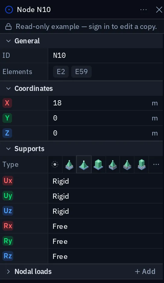
Each of the six is set independently, so those four are presets, not categories. The directions are always the global axes: an inclined bearing has to be modelled with the member geometry, not with a rotated support.
One thing goes beyond the node support:
- Line supports. The same six conditions distributed along a line, with stiffness per unit length, on a whole member or on one edge of a slab. See Elastic foundations.
Choosing an idealisation
Real supports lie between pinned and fixed. Which idealisation is conservative depends on what you are checking:
| You are checking | Conservative choice | Why |
|---|---|---|
| Column and eaves moments | Pinned | With no moment at the base, the column and the eaves joint take it all |
| Frame sway and second-order effects | Pinned | Softer frame, larger deflections |
| Foundation design moment | Fixed | Puts the moment into the foundation |
| Deflection of a supported beam | Pinned | No end restraint to help |
The realistic model of a real base plate is a rotational spring. If you use one, state the stiffness you assumed and where it came from. A reviewer can accept an assumption they can see, not one they have to guess at.
Springs
Springs model soil, bearings, neoprene pads, adjacent structure and any restraint that is neither nothing nor infinite. Units are force per length for translation, moment per radian for rotation, and force per length per unit length on a line support.
Releases
A release removes continuity at one end of one member. Moment releases are the common case: a beam sitting on a bracket, a secondary member that must not attract moment, a truss diagonal that is genuinely pinned.
Releases apply per member, per end, per degree of freedom. Three members meeting at a node can each be released independently, which is what you want where one member is continuous and the others are pinned to it.
Each released direction can be rigid, free, or given a finite stiffness. The semi-rigid connection is the right model for a bolted end plate that is neither a pin nor full continuity.
Releasing both ends
If a member should carry only axial force, use a bar, not a beam released at both ends. Bars have no rotational degrees of freedom to release, so the mechanism cannot arise.
Rigid arms
A rigid arm ties the degrees of freedom of one node to another: an eccentric connection, an offset between a member centreline and its physical bearing. It is a constraint, not a stiff member, so it does not suffer the conditioning problems of a very stiff element.
For a beam sitting off its own centreline (a downstand under a slab, a beam bolted to the side of a column) a member can also carry its own eccentricity, without a separate node and arm.
Checklist
- The structure is restrained in all six global directions, somewhere.
- No member is released at both ends about the same axis.
- Springs act in a plausible direction in every combination: check for uplift.
- The pre-solve model check passed. It catches rigid-body motion, the commonest restraint error, and names the direction that is free.
- Support idealisations are stated in the report, with the reasoning.
- Symmetric structures under symmetric load produce symmetric reactions. If not, the restraints are not what you think.
Something wrong or unclear on this page? Tell us, and it gets corrected.