Hinges
A hinge anywhere along a member, releases at a node, line hinges on plate edges and beams, connected crossings, scissor hinges, hinge results and export.
Modeling 10 min read
A hinge is a release somewhere other than the plain end of a member. A span can be cut at a point, a member can let go of a node it runs through, a slab can turn freely along a wall or a beam, and two bracing diagonals can share a node without bending each other. This page covers each of them, what the results show, and what survives export. The end release itself is on Supports and releases.
| What you want | Tool | What goes into the model |
|---|---|---|
| A pin at a member's end | Model › Connectivity › Hinge start, Hinge end, Hinge both | An end release |
| A hinge partway along a span | Insert hinge… on a beam | The member cut in two, with an end release at the cut |
| One member released at a node it runs through | Releases at nodes in its properties | A release at that node; the member stays whole |
| A plate released along one edge | Model › Connectivity › Line hinge on the edge | A line hinge, LH1, on that plate's edge |
| Every plate released from a beam | Model › Connectivity › Line hinge on the beam | A line hinge on the member |
| Two members joined where they cross | Model › Connectivity › Connect crossings | A shared node, rigid |
| Two diagonals joined by their translations only | Model › Connectivity › Scissor hinge | A shared node, with one beam released there |
A hinge along a member
Right-click a beam and choose Insert hinge…, or use Hinge along… in the End releases section of its properties. The dialog asks for two things:
- Position: the distance From the start, with buttons for the quarter points and for every node already standing on the member. A node already standing there becomes the hinge. The hinge has to lie inside the member.
- Released: what is freed at the hinge, about the member's own axes. A 3D model offers all six directions and starts on and . A plane frame offers , and and starts on .
The app keeps no hinge inside a member. The dialog cuts the member into two at that point, divides its loads between the pieces, and puts an ordinary end release at the end of the first piece, which you can edit later like any other. The two pieces are then two members in tables and design checks. A truss bar has no bending to release, so the command is offered on beams only.
The moment at the hinge drops to zero and the structure carries the load another way. A hand check: two equal spans under hog over the middle support. With a hinge at mid-span of the second span, the moment over that support doubles to .
A release at a node the member runs through
A member can run through a node without being cut there. The Releases at nodes section of its properties has one row per such node. The member stays continuous through the node and keeps carrying its moment past it. What is released is only its hold on the node, so the other members at that node no longer bend or twist it there.
- At a node where no other beam runs through, the switch is Pin: every rotation free, the translations shared.
- At a crossing, the switch is the crossing's Scissor hinge, below.
- The arrow on a row opens the details: each direction Rigid, Free or Spring, in Global X, Y, Z or Custom axes, with Copy from to take the axes of a member at the node.
If nothing else holds the node, the release does nothing, and the model check reports Member release at a node nothing else holds.
Line hinges on plate edges
A line hinge releases one plate along one of its edges from whatever else meets that edge: a wall, another slab, a beam. The other parts on the edge stay as they are. A slab hinged onto a wall is released from the wall; the wall and the slab next to it are not touched.
There are three ways to make one:
- Select plate edges and press Model › Connectivity › Line hinge. Several edges at once make several hinges in one undo step.
- Right-click an edge and choose Line hinge on this edge. The same menu has Remove line hinge once there is one.
- In the properties of a selected edge, press Add in the Line hinge section.
A new hinge frees the rotation about the edge and nothing else. The section gives each direction Rigid, Free or Spring, in the edge's axes: along the edge, normal to the plate, in the plate's plane across the edge. A spring is per metre of edge.
| Direction | Meaning |
|---|---|
| About the edge: the usual hinge | |
| About the line across the edge, in the plate's plane | |
| About the plate's normal | |
| Along the edge | |
| Across the edge, in the plate's plane | |
| Normal to the plate |
In the mesh, the released plate gets its own copy of the edge's nodes, and each copy is tied to its original direction by direction. The copies exist only where something else meets the edge, so a hinge along an edge that a wall reaches for half its length releases that half. An edge met at one point only, such as by a column under it, is left alone. A hinge that nothing meets releases nothing, and the model check reports Line hinge with nothing to release from.
Line hinges are listed under Line hinges in the model tree, with their own ids.
Releasing slabs along a beam
A slab on a downstand beam can stop twisting the beam. Select the beam and press Line hinge, or press Add in the Release from plates section of its properties. Every plate connected to that member is released from it along its length, about the member's axis by default, in one hinge. The plates stay joined to each other. Only their hold on the beam goes.
The directions are along the member () and normal to the plate (), and a spring is per metre of member. Where the plates meet at an angle, as at a ridge beam or a wall under a slab, is the mean of their normals. The beam has to be connected to the plate.
The forces on the edge
A line hinge still passes forces across. In a 3D result viewer showing a plate resultant, with Releases on in Display, each hinge draws its line force along its edge as a diagram, on the same scale as section cuts. The component follows the quantity on show:
| Plate quantity | Line force drawn | Meaning, for the usual hinge |
|---|---|---|
| , | The shear the edge carries across | |
| , , , | Zero, which is the proof that it is a hinge | |
| The twisting moment along the edge | ||
| , , , | The membrane force across the edge | |
| The membrane shear along the edge |
Plate stresses draw no hinge diagram.
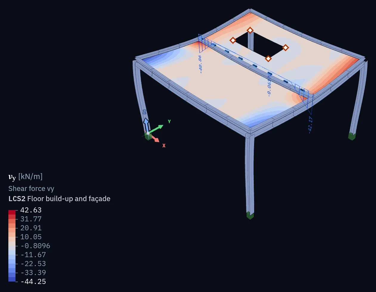
The Hinge results table
Hinge results, under + in the table dock, lists every line hinge with the largest and smallest of , , , , and along it, per metre, in the edge's axes. Selecting a row selects the plate or member it sits on. Results › Output › Export tables offers the same table as Hinge line forces in a model that has line hinges. See Result tables.
Connecting crossings
Members drawn across each other without a node pass each other as if the other were not there. Select them and press Model › Connectivity › Connect crossings. Each pair gets a shared node where it crosses, or where one ends on the other's span, within 1 mm. The connection is rigid.
- A beam stays whole and runs through the new node, so its loads, releases and design settings stay as they were.
- A truss bar cannot run through a node, so it is cut there.
- Two bars crossing in a 3D model are not connected. Four bar ends in one plane with nothing across it would be a mechanism out of that plane.
The model check lists beams that cross without a node as crossings without a shared node, with Connect to join them. Bars passing each other are never listed, since unconnected tension diagonals are usually what is meant. If the crossing is deliberate, dismiss the warning.
To undo a connection later, right-click the node and choose Disconnect the crossing. Disconnect in the ⋯ menu of a row under Releases at nodes takes one beam off the node. Either way the releases there go with it, and a node left holding nothing is deleted.
Scissor hinges
Crossing bracing diagonals are usually bolted to share their translations and nothing else. That halves their buckling length out of plane, and neither bends the other.
Select the two diagonals, or the node where they cross, and press Model › Connectivity › Scissor hinge. They need no node first: the command makes one, joins them there and releases one of them in every rotation, in global axes. The same command is in the right-click menu: Scissor hinge at this crossing on a node, Scissor hinge at the crossing on selected members.
One released beam is all it takes. If every beam at a crossing is released, nothing holds the node itself, and the properties say so and offer Hold the first. The Scissor hinge switch appears in the Releases at nodes section of every beam at the crossing. Switched off from any of them, it is off for all. Where three or more beams cross, the row's details say which of them turn freely and which are held.
Truss bars need no scissor hinge, since they are pinned at a crossing already. A bar crossing a beam is joined by cutting the bar.
The rigid-crossing check
Two beams through a shared node are rigidly joined by default, which is what a floor grillage wants and a bracing panel rarely does. The model check warns Bracing diagonals cross rigidly at N… where two members are diagonals of a panel: they join its opposite corners, and its sides are members. Three sides are enough, since the fourth of a bottom panel is often the ground. Scissor hinge on the warning fixes it in one click. If the two are meant to be continuous through each other, dismiss it.
When hinges make a mechanism
Hinges that open together can leave a node free to move without bending anything. The model check reports Mechanism — hinges let N… move and names the releases and the members. Make one of them rigid, or add a support or a brace. Releases at both ends of one member are covered on Supports and releases.
Display › Releases draws every release in the viewers, line hinges included. Check them there before reading a result.
How hinges export
Hinges outside a member's plain end have no common form in the exchange formats, so the export dialogs warn about each one that the file does not carry.
| Hinge | Project file | IFC | SAF |
|---|---|---|---|
| End release, including a hinge inserted along a member | Yes | Yes | Yes |
| Release at a node, scissor hinge | Yes | In Elementarium's own data only: other programs see the member rigidly connected there | Not exported: SAF writes the member through the node rigidly |
| Line hinge | Yes | Not exported: the slabs are continuous across it in the file | Not exported: the slabs are continuous across it in the file |
On import, a hinge at an interior connection of a beam in an IFC file becomes a hinge here: the beam is cut at that node and released. A hinge that cannot be placed comes in rigid, and the import says so. See IFC and Import & export formats.
Related
Supports and releases covers end releases and rigid arms. Slabs, walls and shells covers how plates connect in the first place. Reading diagrams explains how a hinge shows up in a moment diagram.
Something wrong or unclear on this page? Tell us, and it gets corrected.