Elementarium 0.6 and 0.7: plate results you can design with
Singular points marked on every plate, column heads checked against a 3D model, smoothing that converges — plus ribbed slabs, snap and paste, and Word.
Three releases went out this week: 0.6.0, 0.6.1 and 0.7.0, plus a batch that is live but not yet numbered. Most of it is about one question every slab model raises sooner or later: can I use the number over that column? This post is the answer, with the measurements behind it, and then the rest. The release notes have every line.
The peak that is not a number
Put a point support under a plate, or a column that meets it at one node, or a point load on it, and the bending moment there has no finite value. That is not a solver defect but the theory: under a point force a Kirchhoff or Mindlin plate's moment grows like . Refine the mesh and the peak grows with it, as far as you are willing to go. Re-entrant corners, the ends of line supports and the ends of walls inside a slab behave the same way.
So we measured it. A slab on a point support, read at the support at three element sizes, each half the last:
- raw, at the support node
- mean over a 0.4 m circle
| mₓ at the support, kNm/m | h = 0.2 m | h = 0.1 m | h = 0.05 m | last halving |
|---|---|---|---|---|
| raw, at the support node | 24.7 | 33.1 | 41.3 | +24.8 % |
| mean over a 0.4 m circle | 14.83 | 14.81 | 14.91 | +0.7 % |
The raw value climbs from 24.7 to 41.3 kNm/m and would keep climbing. The mean over a 0.4 m circle round the support reads 14.83, 14.81 and 14.91 kNm/m: a number that does not care about the mesh, and one you can design with.
What 0.6 does about it
Every singular point is marked. Plate results now carry a marker at each point support, point load, column without a head, line-support end, re-entrant corner and member end inside a plate. Amber means nothing deals with the peak; teal means something does. Hover one and the readout says whether its value can be used, and what would fix it. Right-click it to fix it there. See Singular points.
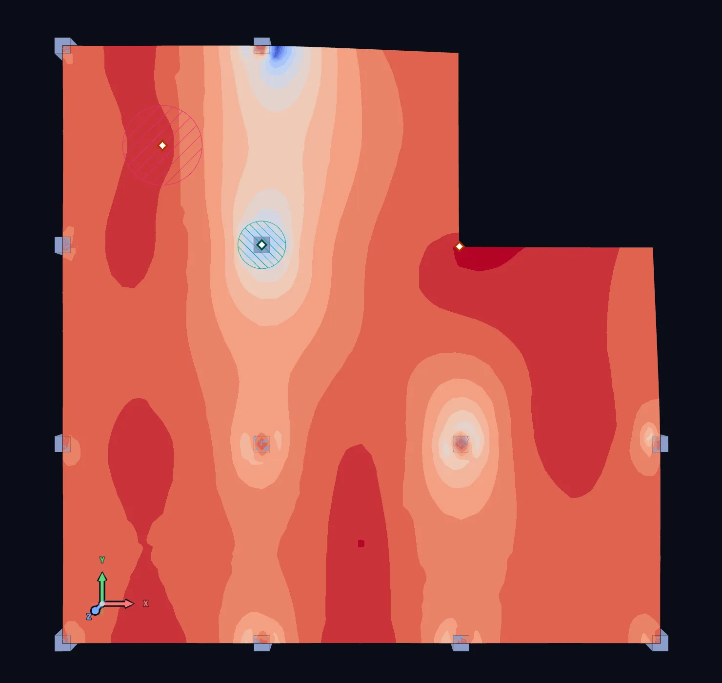
Columns act over their footprint. A column head makes a column bear on the slab over its cross-section instead of at one node, which removes the singularity where it starts. There are three ways to model the footprint, and we checked them against a 3D continuum model of slab and concrete column:
| Column head | Moment at the column face | Column end moment |
|---|---|---|
| Elastic footprint: the slab on a 4 E / t bed over the column | −3 to +9 % | −4 % |
| Rigid footprint: slab bending tied over the column | 13–58 % high, with corner peaks that grow with refinement | — |
New projects use the elastic footprint. The rigid footprint is still there, and so is a stiffened one, the stiff column zone some programs use. Edge and corner columns use the part of the footprint the slab covers. Projects made before 0.6 keep their columns as points, and their results, until you change them.
Point loads spread over a contact area. A wheel or a post base is not a point. A point load can now act over a rectangle or a circle, spread at 45° through the surfacing to the slab's mid-plane as EN 1991-2 §4.3.6 has it, with the total force exact. 10 kN on a 6 × 6 m slab, 0.2 m thick:
- as a point load
- spread over 0.4 × 0.4 m
| |mₓ| under the load, kNm/m | h = 0.2 m | h = 0.1 m | h = 0.05 m | last halving |
|---|---|---|---|---|
| as a point load | −4.10 | −4.78 | −5.45 | +14.0 % |
| spread over 0.4 × 0.4 m | −3.19 | −3.45 | −3.47 | +0.6 % |
Smoothing regions, for the peaks you keep. Sometimes the point support is the right model. A smoothing region is an object of the model on a node, a column, a wall end, an edge or a polygon, with one of four methods: the area average, a ring fit, the value at a column face in the spirit of EN 1992-1-1 §5.3.2.2(4), or zero. It is applied per load case before combination, so combinations stay exact, and it never touches the solve. Each viewer switches between smoothed and raw, and the readout shows the raw peak beside the smoothed value, so nothing is hidden.
Mesh refinements hold a target element size inside a region tied to the model, and grade back to the plate's own size outside it. Measured inside a disk refined to 0.2 m, the average element is 0.201 m.
None of this changes an existing model by surprise. Peak smoothing and automatic refinement are off by default, and column heads apply to new projects only. The one deliberate change is the shell element itself, reworked in 0.6.0 so walls, deep beams and curved shells no longer lock; the release notes say by how much their results move.
Also new
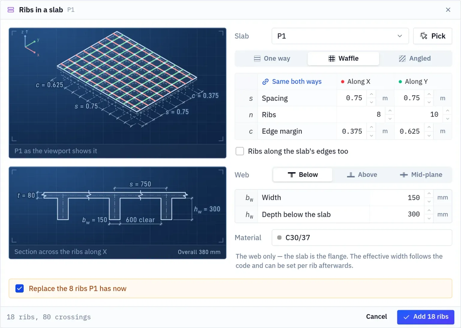
Ribbed slabs. Ribs work as T-beams together with their slab, with the effective width to EN 1992, EN 1994, ACI 318 or AISC 360. Draw them one by one, lay them out one way, as a waffle or at an angle with the Ribs in a slab dialog, or generate the whole slab.
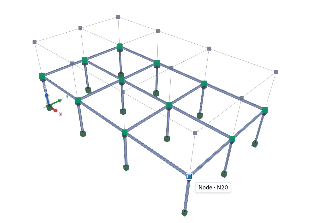
Snap, copy and paste, the CAD way. Object snap to nodes, midpoints, intersections, plate centres and the nearest point on a member, on F3. Copy by a base node and the preview shows the real members, supports and loads where they will land; pasted parts join whatever they touch. A second storey is one copy and one click.
A typeset report. The calculation report is typeset as a PDF with a live preview, instead of going through the browser's print dialog. It can be in Czech, it exports as PDF/A-2b for archiving and building-authority submissions, and on Pro the report, the calculation sheets and the diagrams go to Word with real Word equations.
Viewers that work together. Link viewers and their camera, load case and colour scale move together. Set the ends of a colour scale yourself, edit and save colour maps with the project, and draw a plate result as a surface lifted off the plate.
Section cuts across slabs. Draw a cut across a slab and its results are charted along the line, across every coplanar plate it crosses, with the moment, shear and normal force across the cut integrated over its length.
The smaller things: plate stresses on both faces, with principal and von Mises stresses; results opening as tabs or as tiles side by side; a result board with every quantity on one screen; Elementarium installable as an app from Chrome or Edge; and a Project settings dialog rebuilt as one searchable form, where each setting sits under what it changes — the mesh, the solve, or only the results.
What is next
Concrete design to EN 1992-1-1 is still the most requested gap, and the next module. The plate results above are the ground it stands on: a reinforcement design is only as good as the moment it is given.
To see the singular-point markers on a real model, open the concrete floor, solve it, and plot .