Steel — EN 1993-1-1
Member resistance to §6.2 and §6.3 — what is checked at every station, where buckling lengths come from, and the clauses left to you.
Design checks 8 min read
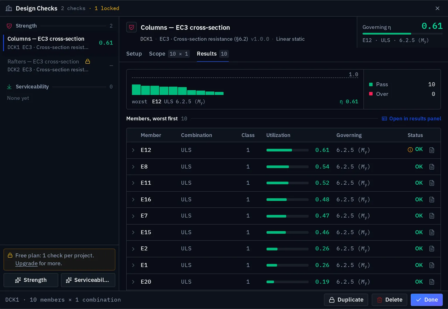
The ec3.member-resistance module verifies steel members to EN 1993-1-1 §6.2 and §6.3:
cross-section resistance at every sampled station, then flexural, torsional and
lateral-torsional buckling of the member between its restraints, and the 6.3.3
interaction. Class 4 sections are verified on their effective section, and slender webs
for shear buckling to EN 1993-1-5. Each utilisation reports its clause, the governing
combination, the position along the member and the fully substituted formula.
New checks use this module. A check created with the older cross-section module keeps it; see The older cross-section module.
Cross-section resistance, §6.2
| Check | Clause | What the module does |
|---|---|---|
| Tension | 6.2.3 | on the gross section |
| Compression | 6.2.4 | , on the effective area for Class 4 |
| Bending | 6.2.5 | about both axes, with the modulus the class allows |
| Shear | 6.2.6 | about both axes, from the section's shear areas |
| Torsion | 6.2.7 | St. Venant , and its reduction of to — eq. 6.26 for I and H, 6.28 for closed sections |
| Bending and shear | 6.2.8 | Moment resistance reduced by where , clamped to 0, 1 |
| Bending and axial | 6.2.9 | See below |
The basic resistances, all divided by :
and each utilisation is the design effect over the resistance, e.g. .
Bending with axial force
Four routes, chosen by what the section actually is:
| Section | Route |
|---|---|
| Class 1 or 2, doubly symmetric I or H | Plastic interaction with the biaxial formula (6.41), , |
| Class 3 | Elastic interaction, §6.2.9.2 eq. (6.42) |
| Class 4 | §6.2.9.3 eq. (6.44) on the effective section |
| Solid Class 1/2 sections, or | The conservative linear form of §6.2.1(7) |
The biaxial plastic interaction (6.41), with :
Class 4 and slender webs
A Class 4 doubly symmetric I or H, or a rectangular hollow section, is verified on the effective section of §6.2.2.5, with plate widths from EN 1993-1-5 §4.4. and replace and in every resistance, §6.3 included. A Class 4 shape the module cannot build an effective section for is refused, with a message: it is the one case a member goes unverified.
A web slender enough to buckle in shear is verified against (EN 1993-1-5 §5) and in bending with shear against (7.1). The check asks whether the girder end has a rigid end post (twin bearing stiffeners or an end plate), because the model does not record stiffeners. The default is the conservative non-rigid column of Table 5.1.
Member stability, §6.3
| Check | Clause | What the module does |
|---|---|---|
| Flexural buckling | 6.3.1 | and from , curve from Table 6.2 |
| Torsional buckling | 6.3.1.4 | for doubly symmetric sections with a known warping constant |
| Lateral-torsional buckling | 6.3.2 | with from the three-factor expression; general route (6.3.2.2) or rolled-section route (6.3.2.3) with its modification |
| Bending and compression | 6.3.3 | (6.61) and (6.62), with the interaction factors of Annex B |
Each resistance is divided by . The buckling curve follows the section's fabrication (rolled, welded, hot-finished or cold-formed hollow), which is set in the section editor; a check can override it for all its members.
Where the buckling lengths come from
Each check chooses where and come from:
| Source | What it does |
|---|---|
| Member factors | and as stored on each member. Nothing is computed. |
| Stability analysis | Each member's from a named buckling analysis: by default from the mode that member takes part in most, or from one mode you pick, or from the lowest for every member (heavily conservative). |
| End-restraint estimate | ENV 1993-1-1 Annex E, from the stiffness of the members framing into each end. Needs no analysis, so it works on an unsolved model and is a second opinion on one that is solved. |
The source and the analysis are stored with the check, so a reopened check reproduces the lengths it was issued with. A or set on the check for one member outranks all three.
The lateral-torsional length always comes from the member, or from a per-member override on the check. A flexural eigenvalue does not say where the compression flange is braced.
Moment gradient, C₁
is derived per member and per combination from the moment diagram, by Serna et al. (2006), the quarter-point formula of AISC F1-1, or the ψ formula of ENV Annex F. It can also be set to 1.0, or entered per member.
Section classification
| Section | How it is classified |
|---|---|
| Doubly symmetric I and H | Table 5.2, from the width-to-thickness ratios of the compressed parts |
| Rectangular hollow and welded box | Table 5.2, with the flat width |
| Solid rectangular and circular | Class 1 by definition — no slender parts |
| Everything else | Verified elastically as Class 3, with a message saying so |
The last row is not automatically safe. A channel, angle or circular hollow section that is really Class 4 is over-estimated as Class 3, so check its class by hand when its walls are thin.
Classification depends on the stress distribution, so the same section can classify differently under different combinations. The check reports the worst class encountered over the stations. See Section classification.
Frame and sign conventions
Local is the member axis. acts about the strong axis and is paired with and ; about the weak axis, with and . is tension-positive. Everything is SI internally (forces in N, moments in N·m, stresses in Pa, lengths in m) and displayed in your unit system.
Partial factors
| Factor | EN recommended | Applies to |
|---|---|---|
| 1.00 | Cross-section resistance, §6.2 | |
| 1.00 | Member buckling resistance, §6.3, and shear buckling | |
| 1.25 | Net section fracture and connections (not checked) |
The national annex may change these, and several do: DIN EN raises to 1.10, the UK NA sets to 1.10, Italy and Norway use . See National annexes.
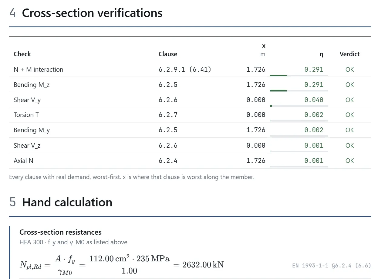
The calculation sheet shows each resistance with the factor substituted, so the factor in use is visible on every line:
Not covered
Each of these is either raised as a message on the check or is a stated assumption of the module:
- Annex A interaction factors. Annex B (Method 2) is implemented. If your national annex requires Annex A, the 6.3.3 result is not the one it asks for.
- Load height in . Loads are taken at the shear centre (, not used), because the model does not record load height. For a load on the top flange this is unconservative, and the check says so.
- End restraint for LTB. : free to warp and free to rotate in plan at the restraints.
- Torsional and flexural-torsional buckling of mono-symmetric sections (channels, tees, angles).
- Torsion–shear interaction for channels. The module uses eq. 6.26, which is written for I and H; a channel takes eq. 6.27 with its warping shear. Check a channel under torsion by hand.
- Warping torsion. The six-degree-of-freedom beam element carries St. Venant torsion only, so an open section under significant torsion needs a dedicated warping analysis.
- Yield strength by thickness. The check uses the of the material. For flanges over 40 mm define a material with the reduced value — see Sections and materials.
- Net section fracture, connections, base plates, fatigue, fire, and cold-formed sections to EN 1993-1-3.
Every utilisation is finite by construction: every division is guarded and the ratio is capped, so an over-utilised member reads as a large finite number, never infinity.
The older cross-section module
ec3.cross-section-resistance verifies §6.2 only, with Class 4 effective sections since its
version 1.1. It stays registered so that checks created with it reproduce the numbers they
were issued with. Such a check offers the upgrade to Member resistance; taking it is your
decision, because adding §6.3 raises the utilisation of every compression member the check
covers. See Module versions.
Also available: AISC 360
The other steel module verifies member strength to AISC 360 Chapters D to H, including compression buckling and lateral-torsional buckling. See Steel — AISC 360.
Something wrong or unclear on this page? Tell us, and it gets corrected.