Your first analysis
Load cases, combinations and a linear static solve — then how to decide whether the answer is trustworthy.
Getting started 3 min read
Solving is the easy part. This guide is mostly about the ten minutes after the solve, where the engineering happens.
Before you solve
Four things need to be true, and the solver can only check the first:
- The model is stable. Every degree of freedom is restrained by something, directly or through stiffness.
- The load cases are pure. Each one contains a single action, unfactored.
- The combinations exist and are current. Generated after the last load case was added.
- Sections and materials are assigned everywhere. A member without a section has no stiffness to contribute.
Running the analysis
Choose linear static and solve. The solver:
- Forms the element stiffness matrices and assembles them.
- Applies the restraints.
- Solves every load case, all of them in one pass.
- Forms each combination as the factored sum of the load-case results.
So the fiftieth combination costs almost nothing compared with the first. See Linear static.
The four checks, in order
Run them in this order. The peaks in step 4 only mean something once the first three pass.
1. The deflected shape
Display the deformed model and amplify it until the deflection is obvious. Ask whether it looks like the structure deflecting. A column that shortens dramatically, a slab that rotates about a corner, a beam hanging below a support that should hold it: all are visible in seconds and invisible in a table.
2. Equilibrium
Compare the sum of reactions with the sum of applied load, per load case. They must agree to within rounding.
3. A hand calculation
Pick the simplest element in the model and check it:
| Situation | Expect |
|---|---|
| Simply supported span, UDL | , , |
| Cantilever, point load at tip | , |
| Fixed-fixed span, UDL | , |
| Axially loaded member |
For a simply supported span the diagram below shows what to look for: the mid-span moment, the end reactions and the deflection.
The point is not precision. It is catching a factor of 1000 in units, a load applied over the wrong length, or a section an order of magnitude off.
4. Only then, the peaks
Now read the governing values.
Reading the results
| Result | What you get |
|---|---|
| Beams and bars | Diagrams of , , along each member, with values at any position |
| Plates and walls | Contours of moments and membrane forces, plus principal values |
| Reactions | Per node, per case, with a total line to compare against the applied load |
| Envelopes | The extreme across a set of combinations. Always ask which combination produced the envelope value (Envelopes) |
Then check the members
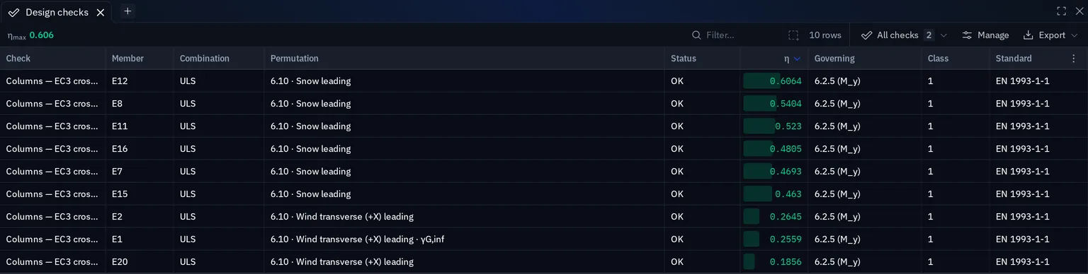
With a trustworthy analysis, run the design checks. Open at least one utilisation ratio fully and read the substituted formula. If the check disagrees with your expectation, the disagreement is visible at clause level instead of hidden behind a number.
What linear static does not tell you
| Question | Where to go |
|---|---|
| Is the structure stable under load? | Linear buckling |
| Will it feel lively? | Modal analysis |
| What do the forces become once the sway is accounted for? | Second-order analysis |
| What happens after first yield or after cracking? | Not covered: material nonlinearity is not in this release |
Something wrong or unclear on this page? Tell us, and it gets corrected.