Sign conventions
Axes, positive directions and how to read a diagram without guessing — the page that prevents most result confusion.
Theory notes 3 min read
Getting a sign convention wrong invalidates everything downstream. Read this once and the "why is this moment negative?" question disappears.
Global axes
A right-handed Cartesian system: and horizontal, vertical and positive upwards. Gravity therefore acts in negative Z, so a downward load is entered as negative in the global system, or as a positive magnitude with a downward direction, depending on how you apply it.
Rotations are positive counter-clockwise about the positive axis, viewed looking back along that axis towards the origin: the standard right-hand rule.
Local member axes
Every member has its own system:
| Axis | Direction |
|---|---|
| Along the member, from start node to end node. Always | |
| , | Perpendicular to and to each other, right-handed. Their orientation is set per member, in the Local coordinate system group of the properties panel |
Two consequences:
- The start node defines the direction of . Draw a member the other way and its local reverses, taking and with it. Two identical columns drawn in opposite directions report moments of opposite sign for the same physical behaviour.
- Which of and is the section's strong axis is a setting, not a given. A column rotated 90° about its own axis bends the other way, and neither the geometry nor the solve will complain. Display local axes before reading or on any member, and orient similar members the same way.
Internal forces
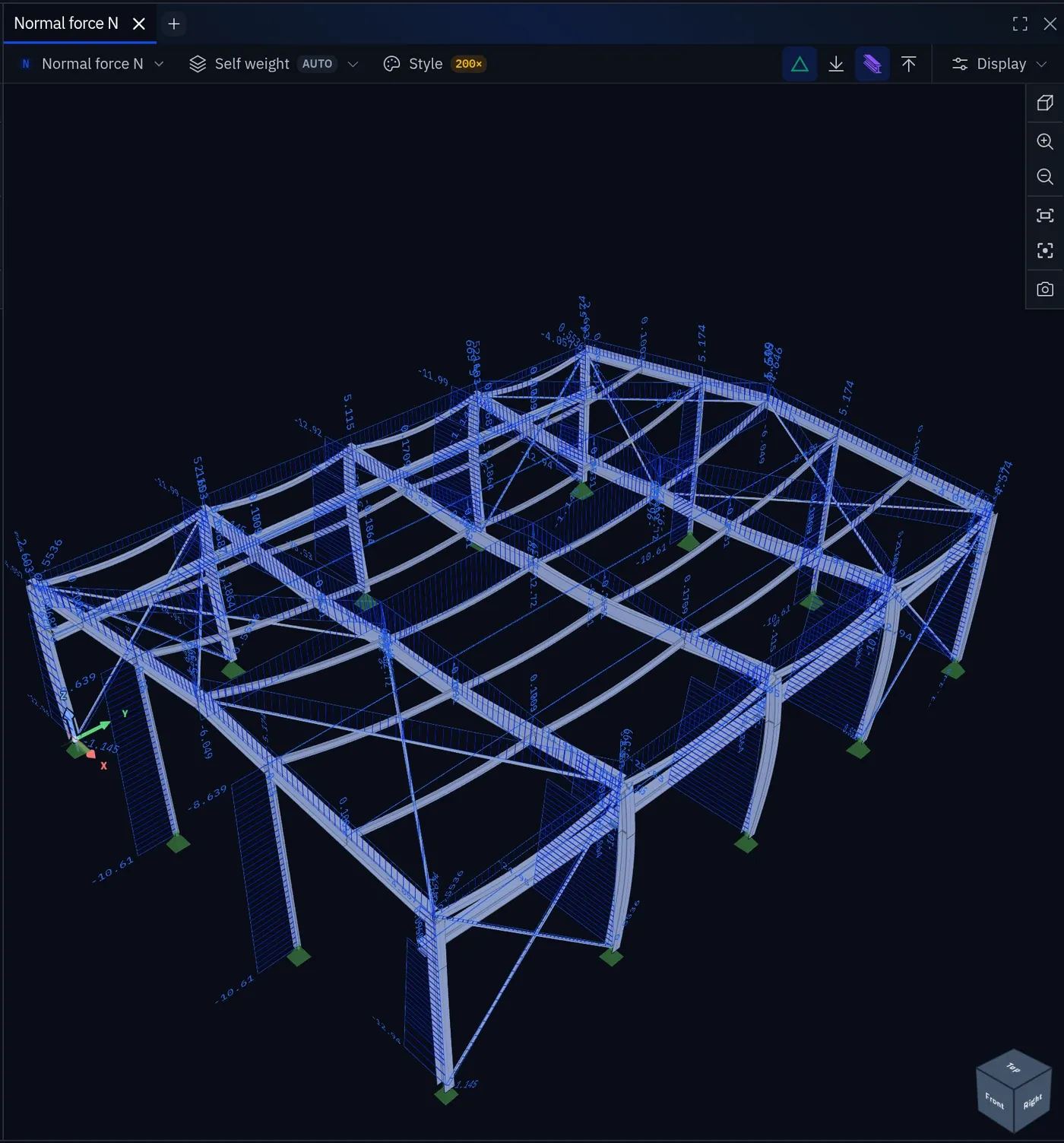
Internal forces are reported in the local system, on the section, using the convention that the values act on the positive face of a cut:
| Quantity | Positive means |
|---|---|
| Tension in the member | |
| , | Shear acting in the positive local or direction on the positive face |
| Torsion about the local axis, by the right-hand rule | |
| Bending about the local axis | |
| Bending about the local axis |
Bending diagram convention
positive corresponds to tension on the positive local face of the section. Whether that face is the top or the bottom of a beam depends on which way its local points, so the sign on its own does not tell you sagging from hogging.
The diagram does. Bending moment diagrams are drawn on the tension side of the member, the convention most European practice uses, so the picture shows directly which face is in tension, whatever the axes:
| Behaviour | Where the diagram is drawn |
|---|---|
| Sagging — tension at the bottom of a beam | Below the beam |
| Hogging — tension at the top of a beam | Above the beam |
Surface results
For plates, walls and shells, results are per unit width in the surface's local system:
| Quantity | Positive means |
|---|---|
| Bending about the local axis, tension on the bottom surface | |
| Bending about the local axis, tension on the bottom surface | |
| Twisting moment | |
| , | Membrane tension |
| In-plane shear |
The surface's local axes come from its definition, so check them before interpreting versus on any surface not aligned with the global axes. "Bottom" means the negative local face of the surface, which for a floor slab modelled the usual way is the soffit.
Reactions
Reactions are reported in the global system and act on the structure. A downward gravity load produces a positive upward vertical reaction. The sum of reactions must balance the sum of applied loads in each direction, per load case: the check described in Your first analysis.
Practical habits
- Draw members consistently (columns bottom-to-top, beams left-to-right) so local axes are predictable across the model.
- Display local axes before interpreting any result on a sloping or rotated member.
Something wrong or unclear on this page? Tell us, and it gets corrected.